Monday, April 15, 2019

Burning Amp BA-3b (Balanced)

Big, hot, heavy, and definitely a keeper. The discussion of the amplifier is on diyAudio.com.

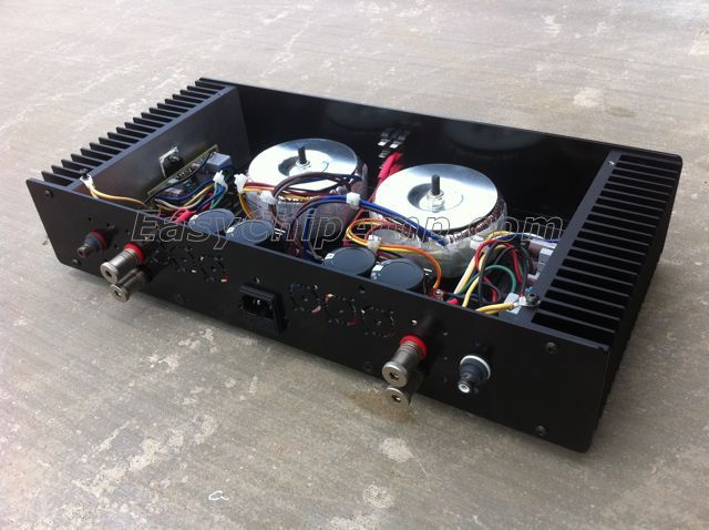
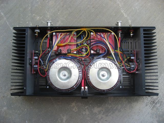
The build is in a 4U/400 case from modushop; each side has two 200mm heatsinks, each holding six MOSFETs (three complementary pairs) and a biasing circuit.

The construction is dual mono, with separate transformers for each channel. Power supplies occupy most of the chassis, while the actual electronics is mounted on the sides.

The power supply was initially CRC filtered, with four 22,000uF Mundorf MLytic® HC High Current Power Caps per channel (pictured).

After successfully fitting my ZenV4-J with CLC filters, I learned how much can be gained by improving power supplies in no- and low-feedback amplifiers, which  have little or no control over output errors and thus poor PSRR. On this premise, I replaced the CRC filters in the power supply of my BA3B with CLCs, so instead of 22mF + (2 x 0.22ohm) + 22mF I now have 100mF + 10mH + 100mF per rail per channel.

The power supply provides +/- 18V rails, with quiescent current set at 3 amps per channel.


Adding TentLabs XO2.2 low jitter clock to exposure 2010S CD player

I added a TentLabs XO2.2 low jitter clock and a separate power supply for it to my Exposure 2010S CD player. The process was very straightforward - see the pictures.

The Exposure 2010S CD player has an easy internal layout, where most of the components sit on a large PCB.

The original clock is based on the 74HC04N chip located in the middle of the PCB, to the left from the three white power connectors connecting the toroidal transformer. A close-up picture shows the crystal resonator wrapped in a black heat-shrink tube, two 33pF capacitors on each side of the resonator (those with black dots on top), and a resistor R75, which also serves in the circuit. The oscillator is built on the single invertor (pins 13 and 12 of the IC).

The original clock is generating 16.9344 MHz at 5V CMOS levels.

To install XO2.2, I removed the resonator and the capacitors, leaving the resistor in place. I connected the signal cable from XO2.2 to the pads of the capacitor that is closer to the pin 14 of the IC; of the two 33pF capacitors, it is the farthest from the front of the CD player. Then I glued the XO and the power supply boards to the right of the main board, closer to the front panel. I could probably drill the bottom plate and use screws, but I didn't.

The power supply is connected to the mains switch with two wires (red on my photo) that go along the front panel near the bottom and are soldered to the small PCB holding the on/off switch on the left side of the panel.

That's it! It took me maybe two hours altogether.

My impression is that with the XO, the sound became richer in details and more transparent, with better spatial resolution. Obviously, this is very subjective; no double-blind comparison could be performed on just one CD player being modified.

P.S. I also had to replace the "analogue output" double PCB mounted RCA connector, as its ground pin broke. I installed two panel mounter RCAs, seen in the photo.


CD transport

A CD transport with a Philips CD Pro 2LF mechanism purchased from Enco - they still have it available! Built in 2011 from a Chinese kit with the enclosure matching the DAC from the previous post. As in the DAC, extra thick copper and machined aluminum do not add up to great performance. Nice remote, though.


Hifidiy.net DAC

Built from a kit in 2011.

The design is a typical oversampling DAC of the era: S/PDIF receiver is followed by an asynchronous sample rate converter, followed by a PCM1794 DAC - quite similar to my ezDAC (see an earlier post). The USB interface is built around TI's PCM270x chip. A fancy addition is a tube buffer. The construction is very solid with thick aluminum panels.

I know this is subjective, but I don't like the sound at all. Unfortunately, I can say this about every single eBay kit or PCB I have ever purchased. They all feature pretty PCBs with extra thick copper, machined aluminum panels and, in this case, an R-core power transformer, they promise big ticket performance on the cheap, but they do not deliver. The good sound is not in thick copper or solid aluminum enclosure.


Grounded Grid Preamp

Built from the kit from Transcendent Sound (Bruce Rozenblit). It sounds very nice, but is not being used - in stock form, it has too much gain for any of my systems.


Yet another Super Gain Clone

Unsatisfied with the sound of my gainclone amplifier (see an earlier post), I re-used the enclosure and the power supply for a gainclone along the lines suggested by Bob Cordell, whose implementation of an LM3886 based amp was praised by at least one member on the NJ audio society. Quote:"Bob showcased the Super GC at the NJ Audio Society and it sounded fantastic."

I skipped both the Klever Klipper and the toroidal air core output inductor, and kept only 10,000 uF per rail in the PSU. The schematic can be found in Chapter 27 of Cordell's Designing Audio Power Amplifiers. The PCB was designed to re-use the existing mounting holes of the ChipAmp's PCB.

The result? Better than with a plain vanilla chip amp, but IMHO still not good enough for music. Perhaps I should not have limited myself to re-use of the PSU et al. but should have taken all the details of my implementation seriously.

That was 2011. Looking back from 2019, I know I can do better! For more details, check out this discussion at diyAudio.com and my boards on sale.


Monday, April 1, 2019

DCPP aka Engineer's Amplifier

In early 2011, I built a Distortion Cancelling Push Pull (DCPP) amplifier designed by Peter Millett. It sounds very nice, was fairly easy to build, and is rather inexpensive. Thank you Peter for the great design!


Sunday, March 31, 2019

Burning Amp 1

To get warm and comfortable on long winter evenings, in the end of 2010 I built myself a Burning Amplifier 1. With its 300W quiescent dissipation and ineffable ((c) Nelson Pass) sound, it is a nice winter time companion.

The enclosure, heatsinks and fans, power supply and speaker protection were salvaged from  my previous (not documented and hence not posted) attempt to build a Krell KSA-50 clone. The Krell clone worked but sounded strange, and I did not have the skills at the time to make it right.

I used four heatsinks, each holding two IRF250 MOSFETs in TO-3 packages and a PCB. Each pair of heatsinks is cooled by a quiet 140mm fan. Power supply uses a 400W toroidal transformer and 2x40,000 uF per channel; it is a dual mono configuration. The amplifier is housed in a 5U 400mm deep enclosure from modushop. Their "pierced" (perforated) base plate was very handy to keep all the parts together without sacrificing the looks. Total weight is about 50 pounds.

The knob on the front panel was designed as volume control, but it looked ugly, so I later remove it and replaced with a ON/OFF button.


Saturday, March 30, 2019

LME49830 + 2SK1530 + 2SJ201

This was an implementation of National Semiconductor's reference design for LME49830 (now obsolete) with two matched pairs of Toshiba's 2SK1530+2SJ201 (also obsolete) per channel. As National Semiconductor in 2011 became part of Texas Instruments, this became a truly obsolete build.

The design is documented in two National Semiconductor's application notes, AN1849 for the power supply and AN1850 for the amplifier - the latter is unavailable from TI. The PCBs were made using National's gerbers for the amplifier and the power supply, thus National's logos.

The amp sounds surprisingly good, so good that I rebuilt is as a pair of monoblocks, each delivering healthy 200W into 8 ohms. It now looks much tidier; I will post the pictures of the monoblocks later.


Yet another Gainclone

This was unavoidable, I guess. Dual mono LM3886 kit from ChipAmp.com (the site is down) with Avel Lindberg's transformers in a wonderfully compact enclosure from Design Build Listen. I liked the simplicity but not the sound.

However, this project started the whole line of exploration of how implementation of opamp circuits affects the audible and measurable performance of those circuits and eventually led to HiFiOcean. I now make and offer Gainclone boards that sound and measure much better.