Tuesday, September 13, 2022

High Precision Composite Op-Amps, Part 3 - More Loop Gain

This post is a part of the series on audio amplifier feedback. The contents of the series can be found here.

As discussed in my previous post on this topic, the resistive voltage divider in John D. Yewen's composite amplifier (see his article "High-precision composite op-amps" in Electronics & Wireless World, February 1987):

adds a zero to the loop gain, which helps to achieve stability at the expense of the loop gain:

For audio applications, it is desirable to maximize the loop gain, at least in the audio band, but preserve the phase margin. One way to keep that zero and maximize the loop gain at audio frequencies is to make the voltage divider frequency dependent, for example:

Adding an inductor in parallel to R3 adds a pole-zero pair (disregarding the inductor's own series resistance, the pole is at $F_p={1 \over {2 \pi}} {{R_3 || R_4} \over L_1}$, the zero at $F_z={1 \over {2 \pi}} {R_3 \over L_1}$). With the values shown, we get about 12dB of extra loop gain at 20kHz with the same phase margin as without the inductor:

 A 22mH inductor may not be very practical, but a similar effect can be achieved with a resistive-capacitive divider, for example:

Here, the pole is at $F_p={1 \over {2 \pi R_5 (C_1 + C_2)}}$, the zero at $F_z={1 \over {2 \pi R_5 C_1}}$. With the values shown, the loop gain is about the same as with the inductor above:


Not bad for one additional passive component. It works in hardware, too - I will show a practical example in my next post.


Tuesday, September 6, 2022

High Precision Composite Op-Amps, Part 2 - Divide and Conquer

This post is a part of the series on audio amplifier feedback. The contents of the series can be found here.

My previous post on this topic was on composite opamps from by John D. Yewen's article "High-precision composite op-amps" (Electronics & Wireless World, February 1987):

Appropriately choosing the voltage divider R1R2 at the output of U1 allows to achieve stability (obtain sufficient gain and phase margins) of the composite at the expense of the loop gain. Here, orange traces are the loop gain of the composite from the schematic above, while blue are the maximum possible (whether stable or not) loop gain with the same two opamps:

How can a simple resistive divider make the composite stable? Let me look at the role of the voltage divider in Yewen's composite.

Referring to the schematic above, U2 sees a (differential) input signal that is a sum of (i) the signal at the non-inverting output, where Ri and Rf connect, and (ii) the same signal amplifier by U1 and divided by R1R2.

At low frequencies, U1's gain is large, and U2's input signal is effectively that at its non-inverting input. The loop gain is the product of that of U1 and U2 and falls with frequency at 40dB/decade. At high frequencies, U1's gain is small, and U2's input signal is effectively that at its inverting input. The loop gain is just that of U2, falling at 20dB/decade.

The transition from "low" to "high" frequencies is a zero in the composite's loop gain, located at the frequency where the signal magnitudes at the non-inverting and inverting inputs of U2 are equal - that is, when the gain of U2 followed by R1R2 is unity. For a single-pole U1, that frequency is a fraction of U1's Gain Bandwidth Product (GBW):$$F_{zero}=GBW_{U_1} \times {R_2 \over {R_1+R_2}}$$In the example above, GBW is 10MHz, the divider's attenuation is 22, so the zero is at ${{10 MHz}\over 22} = {455 kHz}$.

That is, Yewen's voltage divider sets the frequency of a zero in the composite's loop gain. The higher the attenuation in the divider, the lower is the zero, and vice versa.

By the way, it is possible and quite practical to replace the fixed divider with a trimpot and adjust the zero to one's liking, e.g. to obtain the necessary phase margin.

Can we make it still better? Yes we can! Stay tuned...

Tuesday, June 14, 2022

Omicron Headphone Amplifier: Circuit Design

As I mentioned in the previous post, the idea was to build a compact, inexpensive, easy to build low distortion headamp.

One can do compact with discrete SMT circuitry, but that would not be easy to build, hence Omicron is built with opamps.

Common, easily available, inexpensive opamps may or may not be able to drive 32ohm cans directly, so Omicron needs a current booster. An integrated high-speed buffer such as BUF634, LME49600 or LT1010 would do the job, but you can get 10 opamps for the price. So the booster is a classic push-pull emitter follower - just two transistors.

In a circuit like that, there are two major sources of distortion under designer's control. The obvious one is the output stage, where transistors experience large variations of voltage and current, leading to nonlinearity and to distortion. Since we only need 100mW - that's 80mA peak into 32ohm or 11V peak into 600ohm - and it is not a battery-powered headamp, Class A or AB with sufficient quiescent current is an easy choice. Unfortunately, even Class A by itself does not deliver the distortion we have in mind, so we will place it inside a feedback loop.

Quite a few headamps use a current booster inside the feedback loop of an opamp. It works well at low frequencies, below 1kHz or so, but at higher frequencies the opamp's gain goes down, and distortion goes up. This produces familiar looking charts:

and familiar sound: feedback redistributes distortion to upper audio frequencies, adding brightness, making sibilants unnatural and muddling the midband with intermodulation products. We want to avoid this trap and push distortion below the noise level using more loop gain. So instead of a single opamp, Omicron uses two (two half of one dual opamp) in each channel.

The other source of distortion is the opamp's input stage. Its has a delicate job of comparing a portion of the amplified signal with that from the source, and its own distortion is indistingushable from the useful signal. Better opamps may have more linear input stages, but are not necessarily common, easily available or inexpensive. Thankfully, there is another way. Increasing the loop gain (which we need anyway) decreases the differential input voltage that the input stage sees, making its job easier and distortion - smaller.

That was for the differential component of the input voltage, but there is also the common mode component. In a typical non-inverting configuration, the differential voltage may be zero, but inverting and non-inverting inputs would be flying up and down with the full amplitude of the input signal. This generates measurable and audible distortion, which we want to avoid. So Omicron is an inverting amplifier.

Inverting, of course, reverses the absolute phase. There are many people who say they can hear absolute phase, and prove this by flipping the phase switch on their amp or reversing speaker connection. However, this is not a blind test and can be (and probably is) biased. A more subtle test was offered by Stereophile on their first Test CD:

Track 8 on the CD features an "absolute phase" demonstration. The sound starts out with its overall polarity one way around, but finishes with its polarity inverted. According to many writers, especially Clark Johnsen in his book The Wood Effect, the sound of human voice and many instruments will be more natural with the polarity correct—ie, so that an acoustic compression that reaches the microphone will be reproduced as an acoustic compression that reaches the listener's ear—than it will the other way. We have no idea which way 'round on Gordon's recording is correct, but as we have inverted the polarity somewhere in the middle, you will be able to hear for yourself if there is an audible difference between the two states. And can you identify where the change in polarity occurs?

If you believe that absolute phase is important, get the CD and listen to the track and find where the change in polarity occurs. If you can do it, then you may want to rewire your headphones 😉

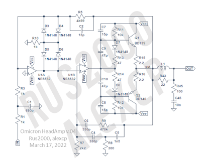
So here is the actual schematic of one channel of Omicron:

Each channel of Omicron is a composite amplifier built with two halves of an NE5532 and a two-transistor complementary emitter follower (EF) as a current booster. There are two feedback loops - one global and one for the second opamp and the EF. This configuration was selected after comparing a number of alternatives, including a single opamp with a current booster, a Yewen style composite, a Samuel-Groner-super-opamp-style composite, and a few others.

Going left to right:
  • R1R3R5C1C2 is the global feedback loop.
  • R1C1 is the input LPF. The amplifier is relatively wideband, with -3dB point of its frequency response at several 100's kHz (measurements will follow).
  • C2 provides lead compensation, improving phase margin.
  • D3-D6 and R10 adjust the loop gain in case of clipping or slewing, helping recovery.
  • R7R8R9C4C5C6 is a local feedback loop with two-pole compensation.
  • Q1Q2 and associated parts are the output current booster. R13 and R14 set the quiescent current, D7 and D8 provide thermal compensation.
  • L1R43R45C45 is the output filter that both helps stability with capacitive loads and protects Omicron from EMI ingressm from the headphones' cable. 

Gain is x2.5, which works for both low- and high-impedance headphones. Input impedance is relatively low at 2kOhm - modern sources will handle it easily. The amplifier does not include a volume control in order not to be tied to a specific part; a 10kOhm pot with linear characteristic can be used - together with the input impedance and the effect on gain, it produces a control characteristic which is closer to true logarithmic than many audio pots.

Stay tunes for measurements and construction details of Omicron.

Wednesday, June 8, 2022

Omicron Headphone Amplifier: Background and Intro

Omicron is a compact, low distortion headphone amplifier that I have been developing jointly with @Rus2000 from the RCL-electro.ru electronics forum. 

I wanted a good sounding headphone amplifier that would meet a few formal requirements:

  • Distortion meaningfully - say by an order of magnitude - lower than that of a reasonable digital source, across the audio band. That means not more than -130dB of distortion.
  • Suitable for headphones from 32ohm (i.e. Grado) to 600ohm (Beyerdynamic T1)
  • At least 100mW of output power to deliver 120dB SPL peaks with the typical 100dB/mW headphones
  • Stable with reasonable capacitive loads, say up to 10nF
  • Common, easily available, inexpensive parts that will not disappear from the market tomorrow (or in a year)
  • Usable by itself, without a hodgepodge of boards - that is, cross-feed, fast DC protection and turn-on delay and  EMI protection are all integrated on board
  • Compact - doesn't need to fit into an Altoids can, but shouldn't be a full 17-inch box either
  • Simple and easy to build, a comfortable weekend project
There are quite a few headamp projects around, yet it is not easy to find something that ticks all the boxes above. Low distortion and garden-variety parts seem to be two most difficult and often conflicting requirements. After looking around for some time, I decided to roll my own.

This is what we got:

  • Outstanding linearity: Distortion better than 100 parts-per-billion (-140dB, 0.000 01%)
  • Compact: Just one IC and two transistors per channel
  • Inexpensive, commonly available parts (NE5532, BD139, BD140), easy through-hole construction
  • Functionally complete: One 80x110mm board carries two channels, DC protection and an optional cross-feed circuit

Simplified schematic:


Some distortion measurements:

In the next post, I will discuss Omicron's amplifier circuit.

Tuesday, May 17, 2022

Which HF distortion measurement: IMD 19+20k or THD 20k?

Here is a (longish) quote from Bruno Putzey's post at the Audio Science Review forum which explains his preference.

Let's start by explaining why I prefer to measure distortion strictly inside the audio band. There is an ongoing controversy about whether signals above 20kHz might or might not be audible, but what is not controversial is that signals below 20kHz are much, much more audible than signals above 20kHz. So if you are in a situation where you have to choose between optimizing performance below 20kHz or above 20kHz, you go for optimizing the bit that we are most likely to hear. Even high-res enthusiasts seem to have tacitly accepted this a long time ago. Remember DSD? A DSD AD/DA converter that, when measured over 20kHz, would easily clock a SINAD of 120dB would "degrade" to 50dB as soon as you upped the measurement bandwidth to 40kHz. But what you heard was of course 120dB, the rest was for the bats. Note the delicious irony. DSD was hawked on the grounds that you needed >20kHz bandwidth for high fidelity, while its skyrocketing supersonic noise floor was excused on the grounds that it was inaudible. As it is, DSD is perfectly listenable. I can find no more eloquent argument that the ear is not very sensitive above 20kHz than DSD...

Anyhow, this is why I like to test amplifiers with test signals that in themselves would be audible (i.e. fit below 20kHz) and also read the distortion and noise only in the band below 20kHz. Of course, I know perfectly well that if you then do a THD versus frequency sweep, any readings above 10kHz are meaningless because even the second harmonic will be outside the audio band. But as our sensitivity to those harmonics drops off rather quickly around 20kHz (as does the ability of most speakers to reproduce them), it's fair to conclude that they do not say much about sound. On the other hand, we can't just go ignoring any underlying non-linearity. We still need to test for misbehaviour at high frequencies. If you choose to limit measurement bandwidth to 20kHz you have to include something like the 19kHz + 20kHz test. I didn't invent that procedure btw, I got that from Bruce Hofer at AP who recommends it. In fact his version is even neater, he uses 19.5kHz and 18.5kHz, making sure that even order products sit at even multiples of 500Hz (from 1kHz upward) while odd products sit at odd multiples of 500Hz, from 17.5kHz down, potentially fitting 37 distinct IMD products inside the band. This refinement doesn't make much difference with the 1ET400 amp of course since there aren't that many IMD products poking up over the noise floor.

Given the choice between a sinewave test at 20kHz which only produces inaudible products and a two-tone test that produces all kinds of in-band distortion I go for the latter. By implication, we should be designing a control loop that maximises loop gain all the way up to 20kHz, but not beyond. Any control system obeys a law called the Bode Inequality. This is the closest we control theorists have to mass-energy conservation. In the case of a class D amplifier it implies that if you maximise loop gain over a largeish fraction of the switching frequency you'll have to take it down really fast afterwards. So that's why the wideband THD vs frequency plot goes up somewhat suddenly at the end. It's a compromise I'm knowingly making. Consider the alternative: I could instead pander to the bat-eared crowd and choose to minimise harmonic distortion components up to 40kHz, say. That would mean accepting a lot less loop gain below 20kHz and hence higher distortion in the audible frequency range. It's not a good tradeoff.

Anyhow, this should explain why the high-frequency IMD spectrum is so much cleaner than a wideband THD test would lead you to expect. But as I see it, the former is the one that is most likely to have a meaningful correlation to sound.

(While I'm at it I ought to point out that the idle noise is noise shaped. This is visible on the broadband noise plots where you can clearly see the rise after 20kHz. The extra outband noise is caused by the comparator and driver chips and ends up being noise shaped by the control loop. I only wanted to mention that because the wideband THD vs F plots are mostly swamped by this HF noise which bore some explaining.)

Tuesday, May 3, 2022

High Precision Composite Op-Amps, Part 1

This post is a part of the series on audio amplifier feedback. The contents of the series can be found here.

In my previous post,  I discussed how distortion can be corrected by cascading multiple opamps:

Obviously, in such a structure the stability problem arises. One possible solution was devised by John D. Yewen and described in his article "High-precision composite op-amps", published by Electronics & Wireless World in February 1987.

Yewen observed that, if every opamp in the schematic above is a perfect integrator (i.e. its open-loop gain falls with frequency at 20dB/decade), the closed-loop transfer function of the above arrangement is simple enough to calculate and to test for stability using the algebraic Routh-Hurwitz stability criterion, without ever looking at Bode plots. Further, the closed-loop transfer function can be manipulated to stability by adding voltage dividers at the outputs of the error correcting opamps:

As for choosing the dividers for stability, Yewen mentions the binomial series (1,1; 1,2,1; 1,3,3,1; ...) and the Butterworth coefficients (1,1; 1,1.41,1; 1,2,2,1; ...) and gives one worked example of a three-opamp unity-gain invertor.

Turns out, the general rule for Yewen's dividers is quite simple for:

  • two- or three-opamp composite amplifiers...
  • with the Butterworth coefficients...
  • built from identical, single pole compensated opamps.

Say, we need an inverting amplifier with gain $(-A)$. For example, in Yewen's worked example above, gain is $(-1)$, so $A=1$. To achieve that, the feedback network $R1R2$ should divide the output signal by ${A+1} = {{R1+R2} \over {R1}} = 2$. Here is the rule:

  • To build a two-opamp composite, add the opamp C1 and divide its output voltage by $(A+1) \times 2$.
  • To build a three-opamp composite, add another opamp C2 and divide its output voltage by $(A+1) \times 4$.

For example, for an inverting composite with $A=2$, the following values will work:

All three circuits above are stable and have phase margin of about 65° (loop gain on the top, closed-loop transfer function at the bottom):


The price for such stability is diminishing returns on extra opamps - each additional error correcting opamp contributes less to the overall loop gain because of the voltage dividers. Also, the closed-loop transfer function peaks around the crossover frequency, so a low-pass input filter is required.

Does it work in practice? Yes, as long as the opamps are (i) identical and (ii) sufficiently close to single-pole, at least around the crossover frequency. Here is a practical composite with the negative gain of 10 and total loop gain of over 90dB, built from four OPA134:


It is quite stable and clips ok:

Can we make it even better? Of course we can. Stay tuned...


Friday, April 22, 2022

Hawksford's Error Corection and "Distortion Selector"

This post is a part of the series on audio amplifier feedback. The contents of the series can be found here.

Hawksford's error correction (H.ec, see my previous post) compares the output signal of a (near-unity gain) output stage with that at its input and adds the difference back to the input, thus correcting the error $\epsilon$ that the output stage introduces:

H.ec is equivalent to the following structure, which sometimes is called a "distortion selector":

"Equivalent" here means that the two schematics above have the same signal transfer function $$STF={H \over {1-B+HB}}$$ and error transfer function $$ETF = {{1-B} \over {1-B+HB}}$$

Ideal compensation in H.ec (i.e. $B \rightarrow 1$) corresponds to an infinite loop gain ${B \over {1-B}} \rightarrow \infty$ of the distortion selector.

Naturally, both H.ec and the distortion selector can be applied not only to a unity gain output stage, but to any amplifier with gain $1 / K$; one just needs to scale appropriately the output signal:

If H is an amplifier with feedback, there is no need to use a separate scaler K; one can use the existing feedback network of H:

It looks a bit complicated, but one practical implementation is straightforward:

Here, A is the "main" amplifier, R1R2 is its feedback network, and C is the distortion selector. Two of the four voltage adders are inside A and C, respectively, and the remaining two are implemented with R1R2.

The distortion selector C by itself is not distortion free, which can be ameliorated by giving it its own distortion selector:

Along the same lines, one can add C3, C4 and so on.

Obviously, in such a structure the stability problem arises. One possible solution was devised by John D. Yewen and described in his article "High-precision composite op-amps", published by Electronics & Wireless World in February 1987. In my next post, I will have a closer look at Yewen's solution.