As I mentioned in the previous post, the idea was to build a compact, inexpensive, easy to build low distortion headamp.
One can do compact with discrete SMT circuitry, but that would not be easy to build, hence Omicron is built with opamps.
Common, easily available, inexpensive opamps may or may not be able to
drive 32ohm cans directly, so Omicron needs a current booster. An
integrated high-speed buffer such as BUF634, LME49600 or LT1010 would do
the job, but you can get 10 opamps for the price. So the booster is a
classic push-pull emitter follower - just two transistors.
In a circuit like that, there are two major sources of distortion under
designer's control. The obvious one is the output stage, where
transistors experience large variations of voltage and current, leading
to nonlinearity and to distortion. Since we only need 100mW - that's
80mA peak into 32ohm or 11V peak into 600ohm - and it is not a
battery-powered headamp, Class A or AB with sufficient quiescent current
is an easy choice. Unfortunately, even Class A by itself does not
deliver the distortion we have in mind, so we will place it inside a
feedback loop.
Quite a few headamps use a current booster inside the feedback loop of
an opamp. It works well at low frequencies, below 1kHz or so, but at
higher frequencies the opamp's gain goes down, and distortion goes up.
This produces familiar looking charts:
and familiar sound: feedback redistributes distortion to upper
audio frequencies, adding brightness, making sibilants unnatural and
muddling the midband with intermodulation products. We want to avoid
this trap and push distortion below the noise level using more loop
gain. So instead of a single opamp, Omicron uses two (two half of one
dual opamp) in each channel.
The other source of distortion is the opamp's input stage. Its has a
delicate job of comparing a portion of the amplified signal with that
from the source, and its own distortion is indistingushable from the
useful signal. Better opamps may have more linear input stages, but are
not necessarily common, easily available or inexpensive. Thankfully,
there is another way. Increasing the loop gain (which we need anyway)
decreases the differential input voltage that the input stage sees,
making its job easier and distortion - smaller.
That was for the differential component of the input voltage, but there is also the common mode
component. In a typical non-inverting configuration, the differential
voltage may be zero, but inverting and non-inverting inputs would be
flying up and down with the full amplitude of the input signal. This
generates measurable and audible distortion, which we want to avoid. So
Omicron is an inverting amplifier.
Inverting, of course, reverses the absolute phase. There are many people
who say they can hear absolute phase, and prove this by flipping the
phase switch on their amp or reversing speaker connection. However, this
is not a blind test and can be (and probably is) biased. A more subtle
test was offered by Stereophile on their first Test CD:
Track 8 on the CD features an "absolute phase" demonstration. The sound starts out with its overall polarity one way around, but finishes with its polarity inverted. According to many writers, especially Clark Johnsen in his book The Wood Effect, the sound of human voice and many instruments will be more natural with the polarity correct—ie, so that an acoustic compression that reaches the microphone will be reproduced as an acoustic compression that reaches the listener's ear—than it will the other way. We have no idea which way 'round on Gordon's recording is correct, but as we have inverted the polarity somewhere in the middle, you will be able to hear for yourself if there is an audible difference between the two states. And can you identify where the change in polarity occurs?
If you believe that absolute phase is important, get the CD and listen to the track and find where the change in polarity occurs. If you can do it, then you may want to rewire your headphones 😉
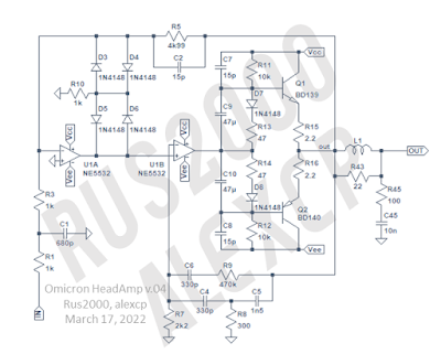
So here is the actual schematic of one channel of Omicron:
- R1R3R5C1C2 is the global feedback loop.
- R1C1 is the input LPF. The amplifier is relatively wideband, with -3dB point of its frequency response at several 100's kHz (measurements will follow).
- C2 provides lead compensation, improving phase margin.
- D3-D6 and R10 adjust the loop gain in case of clipping or slewing, helping recovery.
- R7R8R9C4C5C6 is a local feedback loop with two-pole compensation.
- Q1Q2 and associated parts are the output current booster. R13 and R14 set the quiescent current, D7 and D8 provide thermal compensation.
- L1R43R45C45 is the output filter that both helps stability with capacitive loads and protects Omicron from EMI ingressm from the headphones' cable.
Gain is x2.5, which works for both low- and high-impedance headphones. Input impedance is relatively low at 2kOhm - modern sources will handle it easily. The amplifier does not include a volume control in order not to be tied to a specific part; a 10kOhm pot with linear characteristic can be used - together with the input impedance and the effect on gain, it produces a control characteristic which is closer to true logarithmic than many audio pots.
Stay tunes for measurements and construction details of Omicron.


